Induction Heating Device
Project Overview:
The idea of this product was created in April 2020 after doing an analysis of a consumer need to replace the standard butane torch. The mechanical design and electrical design are near completion allowing for the embedded software development to begin. The ideal candidate should have abundant experience interfacing with microcontroller-integrated peripherals (e.g. PWM, ADC, SPI, I2C) and extensive knowledge of ESP32/STM32 microcontrollers, sensor sampling/conditioning, system time management, and wireless protocols such as Bluetooth & Wi-Fi.
Electrical Schematic
ESP32-c3-mini-1 alternatic
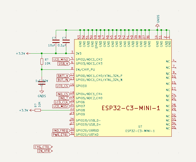
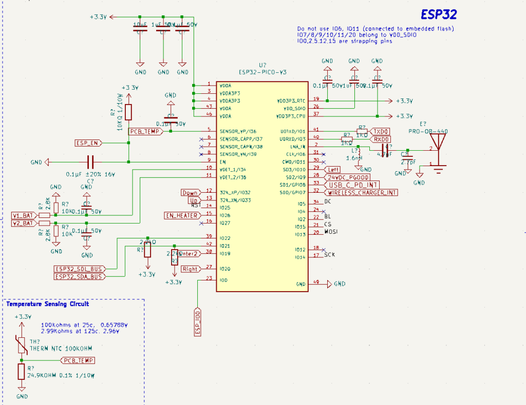
ESP32 and temperature sensing
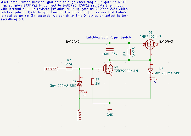
Latching Soft Power Switch
DCDC converter Circuit
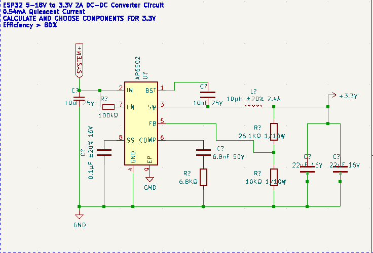
Latching Soft Power Switch
DCDC converter Circuit
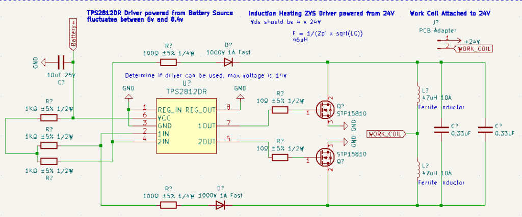
Custom ZVS circuit with mosfet control
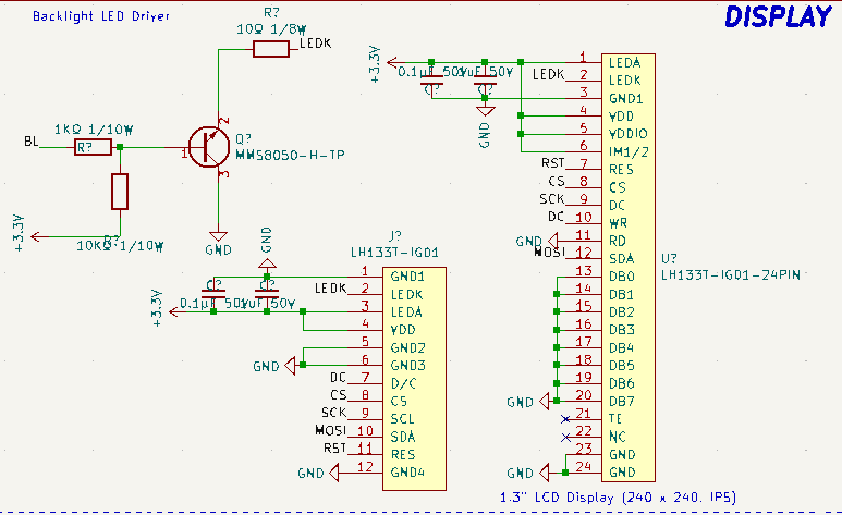
Display
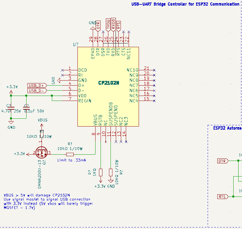
USB-UART controller
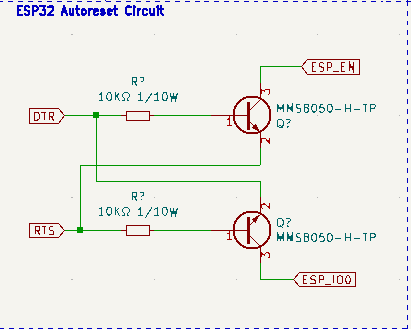
Auto Reset Circuit
USB-UART controller


User interface
- Home Screen: The diagram begins with a home screen that has options for users to interact with different functionalities such as Laser Configuration, Profile Selection, and Settings.
- Profiles: There are multiple profiles which a user can select from. Each profile has its own set of configurations which can include attributes like duration and intensity.
- Settings: The settings seem to allow the user to adjust Wi-Fi connectivity, Bluetooth connections, and software updates. There are also paths to handle different states like connected, not connected, and searching for networks or devices.
- Software Updates: The flowchart has a process to check for software updates which includes different outcomes such as an update being available, an update in process, and handling scenarios where the update fails.
- Connectivity: Both Wi-Fi and Bluetooth connectivity options are present, including the ability to search and select from available networks or devices and to input passwords for secure connections.
- Error Handling: There is a part of the flowchart dedicated to error handling, showing what the interface should do when certain errors occur, like a disconnection or a cancellation.
The color-coding in the flowchart indicates different states or processes, such as green
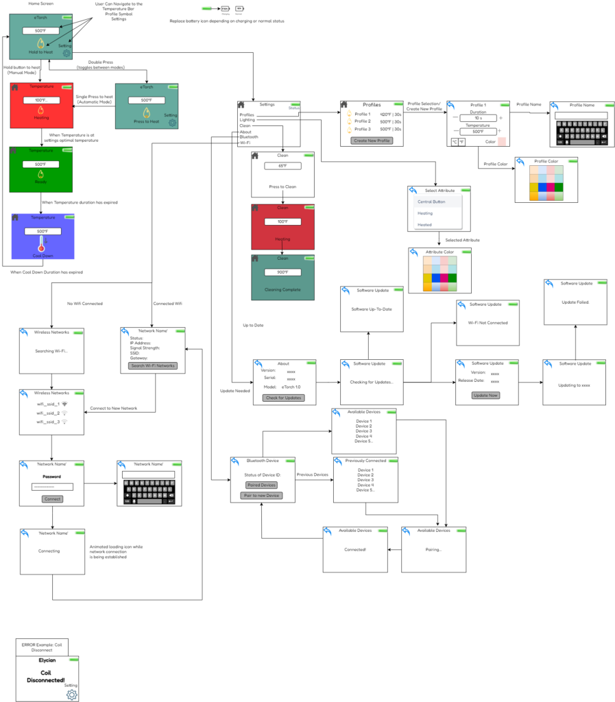
The home screen will consist of a “Settings Icon”, “Heat”, logo, and battery level”.

The user interface will be displayed on a 1.3in TFT IPS 24pin interface screen.
Firmware
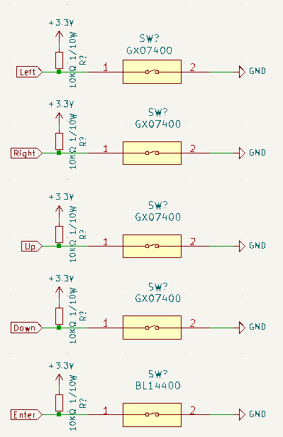
The user control will be a 5-way button. In the middle will be a central Enter button that performs two functions: 1) “select” or proceed with a setting or function illustrated by the display or 2) Perform a microcontroller actuated soft power on/off of the device with 3 quick consecutive button clicks of the central button. Surrounding the middle button are the left, right, up, and down buttons
Manual and Auto heating
Manual Mode will display a page of the desired heating temperature, the Manual
heating icon i.e (), a home button in the upper left corner, a battery percentage in the upper right corner, as well as the current heating. The initial background color for now will be turquoise. The initial status is “Hold to Heat” requiring the user to hold the central button. The user can double click the central button to toggle on the “Press to Heat” option. While the user is holding the central button or has pressed the button (depending on chosen setting), home screen will first change the words “Press to Heat” or “Hold to Heat” to “Waiting for Device”. Once the coil has detected a workpiece then the screen will display “Heating” and the background color will change, for now it will be a breathing red. If the workpiece is not detected for 10s then the screen will display “Could not find Device” for a specified amount of time. While heating the temperature displayed will be the thermistor value read from our coils. Once the thermistor reads the desired temperature set in the settings the heating status will show “Ready” and the background color will change to green. Afterward the user has let go of the button in manual mode, or the specified duration has been reached, then the screen will show a cool down symbol and the text “Cooling Down”. In the case the user is in “Press to Heat” mode and the duration of the profile is not maximized; the user can double click the central button to add 10 seconds to the duration at anytime of the heating process.
Error Handling
Many of the errors have been described above. Additional Errors will be:
Device disconnected from coil.
Device unable to charge.
Incompatible Charger.
Failed to Connect to Bluetooth/Wifi
Unable to heat
Low Battery
ESp32 & Pinout
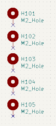
The particular model of the ESP32 used is the ESP32-C3-Mini-1, you can find the datasheet here, do not use any GPIO other than listed in below pinout:
GPIO 0 – ADC, Battery Voltage
GPIO 1 – ADC, Button Input, Left, Right, Up, Down, Enter
GPIO 2 – FSPIQ, LCD DISPLAY MISO
GPIO 3 – ADC, USB Voltage
GPIO 4 – ADC, Induction Current Sense
GPIO 5 – ADC, Induction Temperature
GPIO 6 – FSPICLK, LCD DISPLAY CLK
GPIO 7 – FSPID, LCD DISPLAY MOSI
GPIO 8 – LCD DISPLAY RST
GPIO 9 – Charge Control
GPIO 10 – FSPICS0, LCD DISPLAY CS
GPIO 11 – Induction heat control On/Off
GPIO 20 – Detect Workpiece attached
GPIO 21 – Device Power On/Off
This ESP32 integrates 2 SAR ADCs, ADC measurements are 12-bit and range from 0 V to a user configurable ADC attenuation voltage. Please ensure that all ADC measurements are using ADC_ATTEN_DB_11 which configures the measurable voltage range from 0mV ~ 2500mV.
Please refer to document below for proper ADC readings, including cautions about WiFi interaction.
LCD Display
Use https://lvgl.io/ LVGL graphics library to display interface according to UI diagram seen later in this document. Make sure to use FSPI hardware pins in the following configuration:
MISO: GPIO2
MOSI: GPIO7
RESET: GPIO8
CS: GPIO10
CLK: GPIO6
LCD display controller is ST7789 and is 240×240 pixels.
Heating Control
Converting Thermistor Voltage for Temperature Feedback
Read temperature from thermistor using GPIO5 with variable name heaterTemp. The analog input range is from 0-2.5V which should be converted to temperature in C using formula provided later. Please make software conversion from raw 12-bit values to voltages using equation:
PID Control Loop
The heater circuit should consist of a two-stage PID loop with two forms of feedback: 1) heaterTemp which consists of a PID loop with current command output named outputCurrent, and 2) heaterCurrent which consists of a secondary PID loop with output to the heater Power Stage (using heaterEnable variable linked to GPIO11).
Turn on/off heater using GPIO 11 with variable name heaterEnable and read current using GPIO 4 linked to heaterCurrent. Heater control should be accurate and error minimal, use PID to tune the controller response to changes in temperature. DO NOT use other open-source PID library that does not follow our open-source guidelines. P, I, and D Parameters should be easily accessible and I_CAP should be available for setting as well. It should be easy to configure each coefficient if we decide to change the controller response.
Also implement a variable named powerScale which can be configured from 0 to 100. The default value for this is 100 which represents 100% heater power for a particular output power. This value can be changed to reduce the duty cycle of the heater, thus reducing amount of power used in the heating circuit. In the event of a Power Adapter Warning described later, the powerScale should be automatically reduced until the conditions for the power adapter warning are gone.
The heaterCurrent value should be calculated from a formula that will be provided later.
Alarm Limits
Implement safety limits for the heater temperature, there should be a highTempLim and lowTempLim which we can set easily. The default settings for these should be 0C and 700C respectively. If temperature read from thermistor exceeds either limit, temperature control should be disabled for safety reasons until returning to limit exceeded minus tempHysteresis value. For example if tempHysteresis value = 30C and heaterHighLim = 700C, heater control should not be restored until heaterTemp < heaterHighLim – tempHysteresis = 670C. There should also be a setting control whether temperature is in Fahrenheit or Celsius and this should be additionally accessible by the user settings menu.
Safety Interlock
GPIO20 is False when an open circuit is detected on the heater output (no coil inserted into the induction torch or no metal detected to heat). Heating is only possible when GPIO 20 with variable name workpieceAttached is True – this represents a safety interlock that the hardware is safe to use. An interrupt should be linked to the falling edge signal of workpieceAttached so that the microcontroller instantaneously shuts off heater power if the hardware fails or is unplugged.
Power Adapter Warning
The heater circuit draws power from a USB-C adapter that supplies a maximum of 100W. The current output command OutputCurrent) from the current PID loop should never exceed currentLimit which is automatically set based on voltage read from PowerVoltage before ever enabling the heater control.
powerVoltage is connected to GPIO 3, the reading is on a 8x scale of 0-2.5V analog input reading so that it corresponds to 0-20V USB reading. Voltages read at powerVoltage before the heater output is enabled should correspond to 5V, 9V, 15V, and 20V. The currentLimit variable should be set automatically according to the readings below:
| Actual USB Voltage | powerVoltage Reading | CurrentLimit Setting |
| 5V | 0.625V | 0, turn off the heater, display unsupported adapter warning |
| 9V | 1.125V | 0, turn off the heater, display unsupported adapter warning |
| 15V | 1.875V | 3A |
| 20V | 2.5V | 4A |
powerScale should be proportionally dropped according to any drops in the powerVoltage reading until the powerVoltage reading is stabilized.More c
The current used by the system should be compared over a configurable timescale which will average the reading. For example, heaterCurrent could be 3.4A over a 10ms timespan.
Bluetooth/WiFi Connectivity
Wireless interface to android/IOS applications that allows setting all the values on the induction torch as well as read settings and temperatures.
OTA Software Updates
The ESP32 should be able to monitor firmware versions for updates from an online server such as AWS, the firmware update process must be able to store a backup in case anything goes wrong and revert the update in the event of this. The firmware update should happen directly from the ESP32 through WiFi
General System Monitor
The ESP32 should monitor internal temperature sensor and compare to shutdownTemp and warningTemp. Exceeding warningTemp leads the ESP32 to display a indicator the user and block heating functions and exceeding shutdownTemp shuts off the device.
All analog readings should be filtered over a 3mS timescale, this includes heater temperature, current, etc.
The monitor should implement Coulomb counting to calculate battery percentage variable called batteryCharge displayed on the user interface. Separately, the monitor should read the battery voltage for safety reasons and store under batteryVoltage.The scale of this variable is 4X, so if voltage at ADC pin is 2V, then the actual Battery Voltage is 8V
If batteryVoltage reading exceeds maxBattVolts setting which defaults to 8.2V, then chargeControl should be set to false to prevent the lithium charger from turning on. Otherwise keep chargeControl = True. minBattVolts should default to 7V which corresponds to the voltage at which the system automatically powers Off – turning systemPower to False. Otherwise systemPower should = True. systemPower is linked to GPIO pin 21
The general monitor will also read the status of the buttons according to buttonInput variable linked to GPIO1. The values of buttonInput variable correspond like so:
| buttonInput Reading | Buttons Pressed |
| 0V | No Buttons |
| 0.5V | Enter Button |
| 1V | Left button |
| 1.5V | Right Button |
| 2V | Down Button |
| 2.5V | Up Button |
| Other Voltage | Ignore reading |

